性能指标
相位噪声、杂散以及瞬态响应
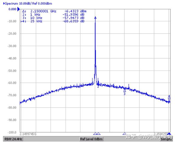
相位噪声
在频域中,这通常被认为是噪声功率相对于载波功率的密度
频谱分析仪测试相位噪声的一个示例。
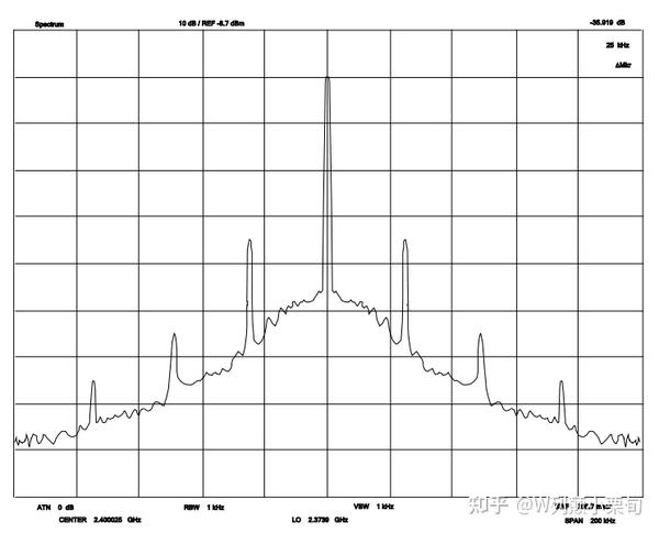
杂散
杂散可以被认为是集中在与载波的特定偏移处的噪声。
杂散有很多种,它们可能有多种原因,但其中大多数发生在非常可预测的偏移处。 杂散倾向于出现在鉴频鉴相器频率、输入参考频率、通道间隔和几分之一通道间隔的倍数处。
在 MIPS 体系结构中,最多支持 4 个协处理器 (Co-Processor)。其中,协处理器 CP0 是体系结构中必须实现的。它起到控制 CPU 的作用。MMU、异常处理、乘除法等功能,都依赖于协处理器 CP0 来实现。它是 MIPS 的精髓之一,也是打开 MIPS 特权级模式的大门。
MIPS 的 CP0 包含 32 个寄存器。关于它们的资料可以参照 MIPS 官方的资料 MIPS32(R) Architecture For Programmers Volume III: The MIPS32(R) Privileged Resource Architecture 的 Chap7 和 Chap8。本文中,仅讨论常见的一些寄存器。
Status,用于处理器状态的控制。Cause,这个寄存器体现了处理器异常发生的原因。EPC,这个寄存器存放异常发生时,系统正在执行的指令的地址。
#查看cp寄存器(openocd)mon mips32 cp0
下面,我们来详解 CP0 中常用的几个寄存器,它们是:BadVAddr,Count/Compare,Status/Cause,EPC,WatchLo/WatchHi。
![[mips 大核手册#^7a2f66]]
其中,Exception 0-5, 8-11, 13, 23 这几个异常类型较为常见。
Exception 0:Interrupt,外部中断。
它是唯一一个异步发生的异常。之所以说中断是异步发生的,是因为相对于其他异常来说,从时序上看,中断的发生是不可预料的,无法确定中断的发生是在流水线的哪一个阶段。MIPS 的五级流水线设计如下:
IF, RD, ALU, MEM, WB。
MIPS 处理器的中断控制部分有这样的设计:
在中断发生时,如果该指令已经完成了 MEM 阶段的操作,则保证该指令执行完毕。反之,则丢弃流水线对这条指令的工作。除 NMI 外,所有的内部或外部硬件中断 (Hardware Interrupt) 均共用这一个异常向量(Exception Vector)。前面提到的 CP0 中的 Counter/Compare 这一对计数寄存器,当 Counter 计数值和 Compare 门限值相等时,即触发一个硬件中断。
Exception 1:TLB Modified,内存修改异常。
如果一块内存在 TLB 映射时,其属性设定为 Read Only,那么,在试图修改这块内存内容时,处理器就会进入这个异常。显然,这个异常是在 Memory 阶段发生的。但是,按 “精确异常” 的原则,在异常发生时,ALU 阶段的操作均无效,也就是说,向内存地址中的写入操作,实际上是不会被真正执行的。这一判断原则,也适用于后面的内存读写相关的异常,包括 TLB Miss/Address Error/Watch 等。
Exception 2/3:TLB Miss Load/Write,
如果试图访问没有在 MMU 的 TLB 中映射的内存地址,会触发这个异常。在支持虚拟内存的操作系统中,这会触发内存的页面倒换,系统的 Exception Handler 会将所需要的内存页从虚拟内存中调入物理内存,并更新相应的 TLB 表项。
Exception 4/5:Address Error Load/Write
如果试图访问一个非对齐的地址,例如 lw/sw 指令的地址非 4 字节对齐,或 lh/sh 的地址非 2 字节对齐,就会触发这个异常。一般地,操作系统在 Exception Handler 中对这个异常的处理,是分开两次读取 / 写入这个地址。虽然一般的操作系统内核都处理了这个异常,最后能够完成期待的操作,但是由于会引起用户态到内核态的切换,以及异常的退出,当这样非对齐操作较多时会严重影响程序的运行效率。因此,编译器在定义局部和全局变量时,都会自动考虑到对齐的情况,而程序员在设计数据结构时,则需要对对齐做特别的斟酌。
Exception 6/7:Instruction/Data Bus Error
一般地原因是 Cache 尚未初始化的时候访问了 Cached 的内存空间所致。因此,要注意在系统上电后,Cache 初始化之前,只访问 Uncached 的地址空间,也就是 0xA0000000-0xBFFFFFFF 这一段。默认地,上电初始化的入口点 0xBFC00000 就位于这一段。(某些 MIPS 实现中可以通过外部硬线连接修改入口点地址,但为了不引发无法预料的问题,不要将入口点地址修改为 Uncached 段以外的地址)
Exception 8:Syscall,系统调用的正规入口,也就是在用户模式下进入内核态的正规方式。
我们可以类比 x86 下 Linux 的系统调用 0x80 来理解它。它是由一条专用指令 syscall 触发的。
Exception 9:Break Point,绝对断点指令。
和 syscall 指令类似,它也是由专用指令 break 触发的。它指示了系统的一些异常情况,编程人员可以在某些不应当出现的异常分支里面加入这个指令,便于及早发现问题和调试。我们可以用高级语言中的 assert 机制来类比理解它。最常见的 Break 异常的子类型为 0x07,它是编译器在编译除法运算时自动加入的。如果除数为 0 则执行一条 break 0x07 指令。这样,当出现被 0 除的情况时,系统就会抛出一个异常,并执行 Coredump,以便于程序员定位除 0 错误的根因。
Exception 10:RI,执行了没有定义的指令,系统就会发生这个异常。
Exception 11,Co-Processor Unaviliable,试图访问的协处理器不存在。比如,在没有实现 CP2 的处理器上执行对 CP2 的操作,就会触发这个异常。
Exception 12,Overflow,算术溢出。会引起这个异常的指令,仅限于加减法中的带符号运算,如 add/addi 这样的指令。因此,一般地,编译器总是将加减法运算编译为 addiu 这样的无符号指令。由于 MIPS 处理异常需要一定的开销,这样可以避免浪费。
Exception 13,Trap,条件断点指令。
它由 trap 系列指令引发。与 Break 指令不同的是,只有满足断点指令中的条件,才会触发这个异常。我们可以类比 x86 下的 int 3 断点异常来理解它。
Exception 14,VCEI,(不明白!谁知道是干嘛使的?)
Exceotion 15,Float Point Exception,浮点协处理器 1 的异常。它由 CP1 自行定义,与 CP1 的具体实现相关。其实就是专门为 CP1 保留的异常入口。
Exception 16,协处理器 2 的异常,和前一个异常一样,是和 CP2 的具体实现相关的。
Exception 23,Watch 异常。前面讲到 Watch 寄存器可以监控一段内存,当访问 / 修改这段内存时,就会触发这个异常。在异常处理例程中,通过异常栈可以反推出是什么地方对这段内存进行了读 / 写操作。这个异常是用来定位内存意外写坏问题的一柄利器。
zMIPS体系结构采用的是 精确异常 处理模式
这是什么意思呢?下面来看从“See MIPS Run”一书中的摘录:
“In a precise-exception CPU, on any exception we get pointed at one instruction(the exception victim). All instructions preceding the exception victim in execution sequence are complete; any work done on the victim and on any subsequent instructions (BNN NOTE: pipeline effects) has no side effects that the software need worry about. The software that handles exceptions can ignore all the timing effects of the CPU’s implementations”
上面的意思其实很简单:在发生这个异常之前的一切计算行为会完整的结束并体现效果。 在发生这个异常之后的一切计算行为(包含当前这条指令)将不会产生任何效果。
另外一种解释是:
A precise exception is one in which the EPC (CP0, Register 14, Select 0) can be used to identify the instruction that caused the exception. For imprecise exceptions, the instruction that caused the exception cannot be identified. Most exceptions are precise. Bus error exceptions may be imprecise.
With the exception of Reset, Soft Reset, NMI, and Debug exceptions, which have their own special processing as described below, exceptions have the same basic processing flow:
• If the EXL bit in the Status register is cleared, theEPC register is loaded with the PC at which execution will be restarted and the BD bit is set appropriately in theCause register. If the instruction is not in the delay slot of a branch, the BD bit inCausewill be cleared and the value loaded into theEPCregister is the current PC. If the instruction is in the delay slot of a branch, the BD bit inCauseis set andEPCis loaded with PC-4.If the EXL bit in theStatus register is set, theEPCregister is not loaded and the BD bit is not changed in theCauseregister.
• The CE and ExcCode fields of the Cause registers are loaded with the values appropriate to the exception. The CE field is loaded, but not defined, for any exception type other than a coprocessor unusable exception.
• The EXL bit is set in the Status register.
• The processor is started at the exception vector.
The value loaded into EPC represents the restart address for the exception and need not be modified by exception handler software in the normal case. Software need not look at the BD bit in the Cause register unless is wishes to identify the address of the instruction that actually caused the exception. Note that individual exception types may load additional information into other registers. This is noted in the description of each exception type below.
EPC中存放的是异常发生时执行的指令地址,或者分支延时发生异常,则存放的是分支的指令地址,不管怎么样,异常处理函数返回都从EPC开始恢复执行,如果在分支延时指令发生异常,则需要在cause寄存器中存放相应标志,这样就可以准确的知道发生异常的指令地址了。
Operation:
1 | ifStatus EXL= 0 then |
As with any procedure, the exception handler must save any registers it may modify, and then restore them before returning control to the interrupted program. Saving registers in memory poses a problem in MIPS:
addressing the memory requires a register (the base register) in which the address is formed. This means that a register must be modified before any register can be saved! The MIPS register usage convention (see Laboratory 4) reserves registers $26 and $27( $k0and$k1 ) for the use of the interrupt handler. This means that the interrupt handler can use these registers without having to save them first. A user program that uses these registers may find them unexpectedly changed.The CPU operates in one of the two possible modes,userandkernel.User programs run in user mode. The CPU enters the kernel mode when an exception happens. Coprocessor 0 can only be used in kernel mode.
llvm项目 https://github.com/llvm/llvm-project , android aosp进行了定制
1 | 这是一个概念 |
scudo 大概分为以下几个部分:
0x10010大小的分配(这个大小还要包括chunk header的大小,且是对齐后的),Primary后端在初始化的时候就会为每个size class mmap 256M的VM(没有commit的)供前端使用。min(2, cpus)),即多个线程共享一个TSD中缓存的内存block。Android 添加了scudo的相关配置, 下面很多地方用到了这里面的配置
1 | struct AndroidSizeClassConfig { |
hexdump -e '4/1 " 0x%02x,"' fdl_sec.bin -n 32
-e 指定格式字符串,格式字符串由单引号包含,格式字符串形如:’a/b “format1” “format2” ‘ 。每个格式字符串由三部分组成,每个由空格分割,如a/b表示,b表示对每b个输入字节应用format1格式,a表示对每个a输入字节应用format2,一般a>b,且b只能为1,2,4,另外a可以省略,省略a=1。format1和format2中可以使用类似printf的格斯字符串。
1 | hexdump -e '16/1 " 0x%02x," "\n" ' keys/aes_priv_key |
-v 打印重复项
如果不带-v, 遇到重复的 会以 * 显示, 带 -v会显示所有项
-n 打印的字节数
-s 忽略文件开头多少个字节,再开始打印数据
因此最终可以使用下面命令完整打印单字节打印二进制文件的数据, 并可以无缝将数据导入到数组中
1 | hexdump -e '16/1 " 0x%02x," "\n" ' -v <file> -n <字节数目> -s <字节数目> |
jemalloc中提供的malloc函数叫做je_malloc, 释放的函数是je_free.
每个 size_class 代表 jemalloc 分配的内存大小,共有 NSIZES(232)?个小类(如果用户申请的大小位于两个小类之间,会取较大的,比如申请14字节,位于8和16字节之间,按16字节分配),分为2大类:
small_class(小内存) : 对于64位机器来说,通常区间是 [8, 14kb],常见的有 8, 16, 32, 48, 64, …, 2kb, 4kb, 8kb,注意为了减少内存碎片并不都是2的次幂,比如如果没有48字节,那当申请33字节时,分配64字节显然会造成约50%的外部碎片large_class(大内存): 对于64位机器来说,通常区间是 [16kb, 7EiB],从 4 * page_size 开始,常见的比如 16kb, 32kb, …, 1mb, 2mb, 4mb等size_index : size 位于 size_class 中的索引号,区间为 [0,231]?,比如8字节则为0,14字节(按16计算)为1,4kb字节为28,当 size 是 small_class 时,size_index 也称作 binind1 | struct base_s { |
用于分配 jemalloc 元数据内存的结构
base.blocks.extent : 存放每个 size_class 的 extent 元数据ind维护的所有的extent元数据信息
下面的参考数据仅是指64位程序的, 32位的配置和64位不同.
M_TSDS_COUNT_MAX
设置线程局部存储(TSL)相关的TSD的数目, M_TSDS_COUNT_MAX设置为8后, 如小于等于8个线程, 每个线程会绑定一个TSD.
在每个线程中 使用malloc free时, 会根据线程状态寄存器查找到其绑定的TSD缓存池.
scudo没有外部配置的情况下, 只有两个TSD缓存池, 在配置M_TSDS_COUNT_MAX后, 会产生最多M_TSDS_COUNT_MAX个缓存池, 该值会影响 small(primary) 分配器. 在TSD缓存池少的情况下, 会出现多个线程共用一个TSD缓存池的情况, 分配释放内存时需要等锁.
Secondary 分配器没有绑定TSD(不是线程私有), 是所有线程共用同一块缓存池, 分配释放需要加锁等锁.
jemalloc5 中 在sz index(36-45范围内的), 当前的配置字节在(14336- 65536)) 使用的缓存是绑定tcache的(线程私有).
M_CACHE_COUNT_MAX
option->MaxCacheEntriesCount
large(Secondary) 分配器在分配释放内存时, 所有线程共用的缓存池的容量, 每次free 时, 会先将该内存单元放到缓存池中, 下次malloc时, 会优先根据分配的size 在缓存池中查找是否有匹配的缓存内存单元, 如果有则直接把该内存单元的地址返回给调用方.
large(Secondary)的缓存池在满了以后, 下一次free时, 会重置清空缓存池
该值对应上图的
EntriesArraySize, 默认值为32, 最大只能设置到256, 如果超过256, 会设置失败, 用默认值.
M_CACHE_SIZE_MAX
option->MaxCacheEntrySize
在free时, large(Secondary) 分配器并不是将所有大于small分配器的内存单元全部放到缓存池中, 而是在 0x40010-M_CACHE_SIZE_MAX范围内的会在free时放到缓存池中(small的范围0-0x40010), malloc时会优先从缓存池中查找. 而大于M_CACHE_SIZE_MAX的malloc则直接走mmap, free走unmap.
该值对应上图的
MaxEntrySize, 默认值是2M
信号是内核提供的向用户态进程发送信息的机制, 常见的有使用SIGUSR1唤醒用户进程执行子程序或发生段错误时使用SIGSEGV保存用户错误现场. 本文以SIGSEGV为例, 详细分析信号使用方法, 内核信号的发送与接收机制.
以下是一个SiGEGV处理例程, 主程序注册一个信号量并创建一个线程, 线程中故意访问空指针, 引发段错误. 在信号回调中会回溯堆栈, 保存出错的地址.
回溯堆栈的原理在分析完整个信号处理流程后再分析, 首先我们先来分析如何使用信号.
sigaction()用于向内核注册一个信号(参数1), 使用参数2(如果非空)作为注册信号的回调, 内核会将之前的信号回调返回在参数3中(如果非空). 如果父进程或程序之前阻塞了该信号则需先调用sigprocmask()取消阻塞.
在回调处理结束时需手动退出进程(exit()), 否则内核会不断触发该信号(重新执行异常指令再次引起崩溃), glibc对SIGSEGV有默认的回调, 所以默认情况下也会正常退出.
1 |
|
虽然用户调用的sig*接口都是glibc的接口, 但实际上glibc还是通过系统调用实现的.
与信号量相关的数据结构有:task_struct(负责保存信号处理句柄, 阻塞与挂起的信号队列)sighand_struct(每个信号处理 handler句柄, 保护信号的自旋锁)signal_struct(信号量结构, 大部分参数都在该结构中)sigpending(挂起队列, 用于索引挂起的信号)
作为一种信息传递机制, 信号量代码本身并不复杂, 即使是信号发送接口__send_signal()(分析见下).
1 | struct task_struct { |
1 | /** |
arm64 有34个寄存器, 包含31个通用寄存器, SP PC CPSR
寄存器中可以存地址, 也可以存值.
| 寄存器 | 位数 | 描述 |
|---|---|---|
| x0-x30 | 64 | 通用寄存器, 可以作 位使用: w0-w30 (访问寄存器的低位) |
| x0-x7 | 64 | 用于子程序调用时参数传递(形参), x0 还用于返回值传递 |
| FP(x29) | 64 | 当前栈帧的栈底 (android上 向上增长), 栈顶地址 < 栈底 |
| LR(x30) | 64 | 程序链接寄存器, 保存子程序结束后需要执行的下一条指令. 即谁调用了当前函数. |
| SP | 64 | 保存栈指针, 使用SP/WSP来进行对栈寄存器的访问 |
| PC | 64 | 程序计数器, 俗称PC指针, 总是指向即将执行的下一条指令, 在arm64中, 软件不能修改pc寄存器 |
| CPSR | 64 | 状态寄存器, NZCV是状态寄存器的条件标志位,分别代表运算过程中产生的状态 |
我们可以根据FP和SP寄存器回溯函数调用过程,通过这两个值,我们可以知道函数的栈起始地址(也就是FP寄存器的值), 以及栈顶(也就是SP寄存器的值)。得到了m函数的栈帧,就很容易从里面提取LR寄存器的值了(FP向下偏移8个字节即为LR),也就知道了谁调用了当前函数。以此类推,可以得到一个完整的函数调用链(一般回溯到 main函数或者线程入口函数就没必要继续了)。实际上,回溯过程中我们并不需要知道栈顶SP,只要FP就够了
https://juejin.im/post/6844903923719864333
x0 ~ x7 分别会存放方法的前 8 个参数;如果参数个数超过了8个,多余的参数会存在栈上,新方法会通过栈来读取。x0 上;如果方法返回值是一个较大的数据结构时,结果会存在 x8 执行的地址上。沿着内存dump的步骤
先忽略tcache的话, 需要关注的结构 je_arenas, arena, bins , bin->slabcur bin->slabs_nofull, bin->slabs_full, je_bin_infos extent_s
1 | p je_arenas |
extent 元信息中关于ind的信息?
extent_szind_get
(extent->e_bits & EXTENT_BITS_SZIND_MASK) >> EXTENT_BITS_SZIND_SHIFT
1 | EXTENT_BITS_ARENA_WIDTH = 12 ; |
1 | e_bits = 29863505920 |
通过rtree 信息直接检索所有的extent
1 | p je_extents_rtree.root #遍历R树 是一个1<<18 容量的数组, root是头指针 |