0%

参考文档
Documentation/devicetree/bindings/interrupt-controller/riscv,imsics.yaml

dts 信息

ex:
提供了两个interrupt file M-mode 和 S-mode的.

1
2
3
4
5
6
7
8
9
10
11
12
13
14
15
16
17
18
19
20
21
22
23
24
25
26
27
28
imsic_mlevel: interrupt-controller@24000000 {
compatible = "riscv,qemu-imsics", "riscv,imsics";
interrupts-extended = <&cpu1_intc 11>,
<&cpu2_intc 11>,
<&cpu3_intc 11>,
<&cpu4_intc 11>;
reg = <0x28000000 0x4000>;
interrupt-controller;
#interrupt-cells = <0>;
msi-controller;
riscv,num-ids = <127>;
};

imsic_slevel: interrupt-controller@28000000 {
compatible = "riscv,qemu-imsics", "riscv,imsics";
interrupts-extended = <&cpu1_intc 9>,
<&cpu2_intc 9>,
<&cpu3_intc 9>,
<&cpu4_intc 9>;
reg = <0x28000000 0x2000>, /* Group0 IMSICs */
<0x29000000 0x2000>; /* Group1 IMSICs */
interrupt-controller;
#interrupt-cells = <0>;
msi-controller;
riscv,num-ids = <127>;
riscv,group-index-bits = <1>;
riscv,group-index-shift = <24>;
};

下面对上述dts的相关属性做一个大概的介绍

  1. interrupts-extended
    对应cpu1-4, 每个cpu都有这两个interrupt file M-mode和S-mode的
    M的对应中断位为11, 代表 Machine external interrupt
    S的对应中断位为9, 代表 Supervisor external interrupt
  2. riscv,num-ids
    Number of interrupt identities supported by IMSIC interrupt file.
    外部中断数量, 反映到eip和eie中, 最小63 最大 2047
  3. riscv,group-index-bits
    Number of group index bits in the MSI target address. When not specified it is assumed to be 0.
    总的group index bits
  4. riscv,group-index-shift
    The least significant bit position of the group index bits in the MSI target address. When not specified it is assumed to be 24.
  5. reg
    Base address of each IMSIC group.
    关于MSI target address:
    从第24 bit 开始, 上述group-index-bits 表示在Group Index中总共有几个bit 被使用
    riscv,group-index-shift 表示Group Index中当前interrupt file 占位开始的那个bit位, 如其占了两个bit位 26-27, shift表示最开始的bit位 26.
1
2
3
4
5
XLEN-1           >=24                                 12    0
| | | |
-------------------------------------------------------------
|xxxxxx|Group Index|xxxxxxxxxxx|HART Index|Guest Index| 0 |
-------------------------------------------------------------

guest os相关

guest external interrupt 相关的dts信息

  1. riscv,num-guest-ids
    Number of interrupt identities are supported by IMSIC guest interrupt
    file. When not specified it is assumed to be same as specified by the
    riscv,num-ids property.
    guest external 硬件中断号 最小63 最大2047
  2. riscv,hart-index-bits
    Number of HART index bits in the MSI target address. When not
    specified it is estimated based on the interrupts-extended property.
    MSI target address 中 Hart Index 总共使用了几个bit位.
    最小0 最大 15
  3. riscv,guest-index-bits
    Number of HART index bits in the MSI target address. When not
    specified it is estimated based on the interrupts-extended property.
    MSI target address 中 Guest Index 总共使用了几个bit位.
    最小0 最大 7
阅读全文 »

Hypervisor Status Register (hstatus)

When VTSR=1, an attempt in VS-mode to execute SRET raises a virtual instruction exception.
When VTW=1 (and assuming mstatus.TW=0), an attempt in VS-mode to execute WFI raises a virtual instruction exception if the WFI does not complete within an implementation-specific, bounded time limit.
When VTVM=1, an attempt in VS-mode to execute SFENCE.VMA or to access CSR satp raises a virtual instruction exception.

The VGEIN (Virtual Guest External Interrupt Number) field selects a guest external interrupt source for VS-level external interrupts. VGEIN is a WLRL field that must be able to hold values between zero and the maximum guest external interrupt number (known as GEILEN), inclusive.
When VGEIN=0, no guest external interrupt source is selected for VS-level external interrupts. GEILEN may be zero, in which case VGEIN may be hardwired to zero.
Guest external interrupts are explained in Section 1.2.4, and the use of VGEIN is covered further in Section 1.2.3.

Field HU (Hypervisor User mode) controls whether the virtual-machine load/store instructions, HLV, HLVX, and HSV, can be used also in U-mode. When HU=1, these instructions can be executed in U-mode the same as in HS-mode. When HU=0, all hypervisor instructions cause an illegal instruction trap in U-mode.

hip & hie

Registers hip and hie are HSXLEN-bit read/write registers that supplement HS-level’s sip and sie respectively. The hip register indicates pending VS-level and hypervisor-specific interrupts, while hie contains enable bits for the same interrupts. As with sip and sie, an interrupt i will be taken in HS-mode if bit i is set in both hip and hie, and if supervisor-level interrupts are globally enabled.

Bits hip.SGEIP and hie.SGEIE are the interrupt-pending and interrupt-enable bits for guest external interrupts at supervisor level (HS-level).
SGEIP is read-only in hip, and is 1 if and only if the bitwise logical-AND of CSRs hgeip and hgeie is nonzero in any bit.

Bits hip.VSEIP and hie.VSEIE are the interrupt-pending and interrupt-enable bits for VS-level external interrupts. VSEIP is read-only in hip, and is the logical-OR of these interrupt sources:

阅读全文 »

内存分配

kmalloc, vmalloc malloc

kmalloc

基于 slab 分配器。 slab 缓存在一个连续物理地址的大块内存上。所以其缓存对象也是物理地址连续的。

vmalloc

仅能保证虚拟地址连续

vmalloc 地址范围

VMALLOC_START
VMALLOC_END

1
2
3
4
5
6
7
8
[    0.000000] Virtual kernel memory layout:
[ 0.000000] fixmap : 0xff1bfffffea00000 - 0xff1bffffff000000 (6144 kB)
[ 0.000000] pci io : 0xff1bffffff000000 - 0xff1c000000000000 ( 16 MB)
[ 0.000000] vmemmap : 0xff1c000000000000 - 0xff20000000000000 (1024 TB)
[ 0.000000] vmalloc : 0xff20000000000000 - 0xff60000000000000 (16384 TB) #vmalloc_start - vmalloc_endl
[ 0.000000] modules : 0xffffffff01576000 - 0xffffffff80000000 (2026 MB)
[ 0.000000] lowmem : 0xff60000000000000 - 0xff600000c0000000 (3072 MB)
[ 0.000000] kernel : 0xffffffff80000000 - 0xffffffffffffffff (2047 MB)
1
2
3
4
5
6
7
8
9
10
11
12
13
14
15
16
17
18
19
20
21
22
23
24
25
-+ vmalloc(unsigned long size)
\ -+ __vmalloc_node(size, align:1, GFP_KERNEL)
\ -+ __vmalloc_node_range(size, align, VMALLOC_START, VMALLOC_END,...)
\ -+ area = __get_vm_area_node(real_size, align, shift, VM_ALLOC | VM_UNINITIALIZED | vm_flags, start, end, node,
\ - struct vm_struct *area = kzalloc_node(sizeof(*area), gfp_mask & GFP_RECLAIM_MASK, node);
| -+ struct vmap_area *va = alloc_vmap_area(size, align, start, end, node, gfp_mask, 0); "在 vmalloc 整个空间中查找一块合适的没有使用的空间 hole"
"查找的地址从 VMALLOC_START 开始, 首先从 vmap_area_root 红黑数上查找, 该树上存放着正在使用的 vmalloc 区块”
“从 VMALOC_START 开始, 查找每个存在的vmalloc 区块的hole能够容纳目前要分配的大小。 如果找到了合适的hole,
调用 __insert_vmap_area 把这个 hole 注册到该红黑树中, 如果没找到hole, 则从最后一个 vmalloc 区块的结束地址开始一个新的 vmalloc 区块"
| -+ setup_vmalloc_vm(area, va, flags, caller); "将该找到的 va 填充到 vm area 中"
| -+ __vmalloc_area_node(area, gfp_mask, prot, shift, node);
\ - area->pages = kmalloc_node(array_size, nested_gfp, node); "分配 area->pages 二维数组指针"
| - area->nr_pages = vm_area_alloc_pages(gfp_mask | __GFP_NOWARN, node, page_order, nr_small_pages, area->pages);
"使用 alloc_page 分配物理页面, 并使用 area->pages 保存这些 page的指针"
| -+ vmap_pages_range(addr, addr + size, prot, area->pages, page_shift); "建立页面映射"
\ -+ vmap_pages_range_noflush(addr, end, prot, pages, page_shift);
\ -+ __vmap_pages_range_noflush(addr, end, prot, pages, page_shift);
\ -+ for i in npages:
\ -+ vmap_range_noflush(addr, addr + (1UL << page_shift), page_to_phys(pages[i]), prot, page_shift); "为每个 pte 建立映射"
"pgd-> p4d -> pud -> pmd -> pte"
\ - pgd = pgd_offset_k(addr); "从 init_mm 中获取 指向 pgd 页面目录项的基址, 然后通过addr 找到对应的pgd 表项"
| -+ flush_cache_vmap(addr, end); "按地址 刷新tlb"
\ -+ flush_tlb_kernel_range(start, end)
\ -+ __flush_tlb_range(struct mm_struct *mm, unsigned long start, unsigned long size, unsigned long stride)
\ - "sfence.vma ..."
阅读全文 »

RISCV start.S uboot 初始化总体框架解析

u-boot 运行在S-mode下

1
2
3
4
5
6
7
8
9
10
11
12
13
14
15
16
17
18
19
20
21
22
23
24
25
26
27
28
29
30
31
32
33
34
35
36
37
38
39
40
41
42
43
44
45
46
47
48
49
50
51
52
53
54
55
56
57
58
59
60
61
62
63
64
65
66
67
68
69
70
71
72
73
74
75
76
77
78
79
80
81
82
83
84
85
86
87
88
89
90
91
92
93
94
+ _start:
\-- mv tp, a0 "tp register save hartid"
|-- csrw   MODE_PREFIX(tvec), t0 "设置中断stvec 入口为 trap_entry"
|-- li t0, SIE_SSIE
|-- csrs   MODE_PREFIX(ie), t0 "设置sie 协处理器, 打开中断, 用来处理ipi 中断"
|-+ call_board_init_f "Set sp in internal/ex RAM to call board_init_f"
\ -- li t1, CONFIG_SYS_INIT_SP_ADDR "设置初始栈基址"
| -- li t0, -16
| -- and    sp, t1, t0 "将堆栈16 bits对齐"
|-+ call_board_init_f_0 "从堆栈开始的地方,为u-boot的global data(struct global_data)分配空间"
\ -- mv a0, sp
| -+ jal board_init_f_alloc_reserve
\ - top -= CONFIG_VAL(SYS_MALLOC_F_LEN) "如定义了CONFIG_SYS_MALLOC_F_LEN,需预留出early malloc所需的空间"
| -- slli t0, tp, CONFIG_STACK_SIZE_SHIFT "tp代表的是hartid, 每个hart 分配STACK_SIZE 空间"
| -- sub sp, a0, t0 "sp = a0 - t0, 地址在初始栈基址上向上增长, a0 初始栈基址 top - malloc空间"
| -- bnez   tp, secondary_hart_loop "其他hart 跳转到 secondary_hart_loop, hart 0 继续"
| -+ jal board_init_f_init_reserve "初始化uboot的global data, 置0"
\ -- "如定义了SYS_MALLOC_F_LEN,则会初始化gd->malloc_base"
| -- jal icache_enable
   | -- jal dcache_enable
   | -+ jalr -> board_init_f "调用board_init_f接口,执行前置的初始化操作" common/board_f.c
    \ -+ initcall_run_list(init_sequence_f) "执行init_sequence_f" 里的一系列初始化函数
    \ -+ init_sequence_f
    \ -- initf_malloc
    | -- arch_cpu_init
    | -- arch_cpu_init_dm
    | -- timer_init
    | -- env_init
    | -- console_init_f
    | -- print_cpuinfo
    | -- dram_init
    | -- ..
    | -- reloc_fdt
    | -- reloc_bootstage
    | -- setup_reloc
    | -+ jump_to_copy
    \ -+ relocate_code(gd->start_addr_sp, gd->new_gd, gd->relocaddr) "开始进行主核relocate"
    \ -- mv s2, a0          /* save addr_sp */
    | -- mv s3, a1          /* save addr of gd */
    | -- mv s4, a2          /* save addr of destination */
    | -+ stack_setup
    \ -- slli   t0, tp, CONFIG_STACK_SIZE_SHIFT
    | -- sub    sp, s2, t0 "gd->start_addr_sp - offset(of hartid)"
    设置新的sp, 这个sp 是reloc 后的sp "gd->start_addr_sp = gd->relocaddr;"
    | -- clear_bss clbss_l "将__bss_start到__bss_end" 之间reloc 到 ram上的bss 区段清0
    | -- copy_loop "reloc 将_start到_bss_start之间的代码段拷贝到 relocaddr处"
    | -+ fix_rela_dyn "Update dynamic relocations after board_init_f"
    | -+ relocate_secondary_harts
    \ -- la  t0, secondary_hart_relocate
    | -- add a0, t0, t6 "到reloc 地址上执行secondary_hart_relocate"
    a0 为 secondary_hart_relocate
    | -- mv a1, s2 "s2 为 addr_sp"
    | -- mv a2, s3 "s3 为 gd 指针"
    | -+ jal    smp_call_function
    \ -+ send_ipi_many(&ipi); "发送ipi中断", 前面传的三个参数保存在 gd->arch.ipi 中
    \ -+ riscv_send_ipi(reg) "reg为从uboot fdt中查到的所有的hart"
    \ -- SBI_CALL_1(SBI_SEND_IPI, hart_mask);
    "调用opensbi的函数, 给指定的hart发送ipi中断"
    -----------------------------ipi中断, 跳入其他核----------------------------------------------
    | -+ secondary_hart_loop "其他hart处在secondary_hart_loop 处调了 wfi 等待"
    \ -- csrr   t0, MODE_PREFIX(ip) "读sip"
    | -- andi   t0, t0, SIE_SSIE
    | -- mv a0, tp "hartid 为第一个参数"
    | -+ jal handle_ipi "如果来了software 中断, 即会跳到 handle_ipi 处理, 否则继续 secondary_hart_loop"
    \-+ handle_ipi(hartid) "对应的hart 收到ipi 中断"
    \ -- riscv_clear_ipi(hart); "会导致 mip.SSIP = sip.SSIP 清0"
    | -- invalidate_icache_all();
    | -- smp_function = gd->arch.ipi[hart].addr;
    "此处为传递的第一个参数, secondary_hart_relocate"
    | -+ smp_function(hart, gd->arch.ipi[hart].arg0, gd->arch.ipi[hart].arg1);
    \ -+ secondary_hart_relocate
    \ -- slli   t0, tp, CONFIG_STACK_SIZE_SHIFT
    | -- sub    sp, a1, t0 "a1 为 new_sp, new_sp - offset(of hartid)"
    | -- mv gp, a2 "更新gd指针到gp寄存器"
    | -- secondary_hart_loop wfi
    "其他核响应完ipi后, 只更新了sp和gp, 然后继续挂起等待"
    ---------------------------------回主核-------------------------------------------------
    | -+ call_board_init_r
    \ -- jal invalidate_icache_all
    | -- jal flush_dcache_all
    | -- mv  a0, s3          /* gd_t */
    | -- mv  a1, s4          /* dest_addr */
    | -+ jalr -> board_init_r "跳转到reloc board_init_r执行"
    \ -+ initcall_run_list(init_sequence_r)
    \ -+ init_sequence_r
    \ -- initr_reloc_global_data
    | -- initr_barrier
    | -- bootstage_relocate
    | -- board_init
    | -- arch_early_init_r
    | -- initr_secondary_cpu
    | -- interrupt_init
    | -- board_late_init "board 相关修改"
    | -+ run_main_loop "loop 等待接收输入的命令"

上述过程中, riscv_send_ipi 发送ipi 中断给其他核, 其他核是在M-mode 的opensbi 下处理的ipi中断, 处理时会调用sbi_ipi_process_smode 函数将 MIP.SSIP 置位, 因为开启了mideleg的 MIP_SSIP 位, 会导致sip.SSIP 也会被置位. 返回给uboot后, 从核在secondary_hart_loop 中loop, 判断sip.SSIP & sie.SSIE, 这个时候都置位了, 从核跳出secondary_hart_loop, 执行后面的handle_ipi 函数

u-boot 设计规范

u-boot是一个bootloader,有些情况下,它可能位于系统的只读存储器(ROM或者flash)中,并从那里开始执行。
因此,这种情况下,在u-boot执行的前期(在将自己copy到可读写的存储器之前),它所在的存储空间,是不可写的,这会有两个问题:

  1. 堆栈无法使用,无法执行函数调用,也即C环境不可用。
  2. 没有data段(或者正确初始化的data段)可用,不同函数或者代码之间,无法通过全局变量的形式共享数据。
    对于问题1,通常的解决方案是:
    u-boot运行起来之后,在那些不需要执行任何初始化动作即可使用的、可读写的存储区域,开辟一段堆栈(stack)空间。
    一般来说,大部分的平台,都有自己的SRAM,可用作堆栈空间。如果实在不行,也有可借用CPU的data cache的方法(不再过多说明)。

对于问题2,解决方案要稍微复杂一些:
首先,对于开发者来说,在u-boot被拷贝到可读写的RAM(这个动作称作relocation)之前,永远不要使用全局变量。
其次,在relocation之前,不同模块之间,确实有通过全局变量的形式传递数据的需求。怎么办?这就是global data需要解决的事情。

为了在relocation前通过全局变量的形式传递数据,u-boot设计了一个巧妙的方法:

  1. 定义一个struct global_data类型的数据结构,里面保存了各色各样需要传递的数据

  2. 堆栈配置好之后,在堆栈开始的位置,为struct global_data预留空间(可参考后面的说明),并将开始地址(就是一个struct global_data指针)保存在一个寄存器中,后续的传递,都是通过保存在寄存器中的指针实现

    board_init_f_alloc_reserve 的返回值(a0)就是global data的指针

阅读全文 »

注意: 下面的操作步骤, 开发板不要插 sd 卡

配置tftpd

1
2
3
4
5
6
7
8
9
10
sudo apt install tftpd-hpa
sudo vi /etc/default/tftpd-hpa #编辑 /etc/default/tftpd-hpa
# /etc/default/tftpd-hpa

TFTP_USERNAME="tftp"
TFTP_DIRECTORY="/srv/tftp"
TFTP_ADDRESS=":69"
TFTP_OPTIONS="-s"

sudo chmod 777 -R /srv/tftp

配置完后, tftp 使用的目录为 /srv/tftp

下载 https://cloud.hexintek.com:10003/d/f/731200443442580601 visionfive2_fw_payload.img 拷贝到该文件夹中

1
sudo cp visionfive2_fw_payload.img /srv/tftp

本机测试

1
2
tftp localhost
> get visionfive2_fw_payload.img

无错误代表没问题

配置toolchain

阅读全文 »

本地仓库
git init
git add …
git commit

git branch

关联远程分支

1
git remote add origin "ssh://liguang.zhang@web.hexintek.com:29418/android/library/crypto-proxy"

远程分支与本地分支合并

1
git pull --rebase origin master

批量修改远程提交

批量修改本地未上库的提交

1
git rebase -i origin/master

需要将每一笔提交改为 edit 状态

阅读全文 »

主要介绍怎样将crypto hardware accelerate 移植到 linux crypto api中
参考项主要是 stm32的实现

crypto中移植aes 引擎

linux中 hardware ip 是以驱动的方式加载到kernel中的
先看一下驱动的定义

1
2
3
4
5
6
7
8
9
10
11
12
13
14
static const struct of_device_id stm32_dt_ids[] = {
{ .compatible = "st,stm32f756-cryp", .data = &f7_data},
{ .compatible = "st,stm32mp1-cryp", .data = &mp1_data},
{},
};
static struct platform_driver stm32_cryp_driver = {
    .probe  = stm32_cryp_probe,
    .remove = stm32_cryp_remove,
    .driver = {
        .name           = DRIVER_NAME,
        .pm     = &stm32_cryp_pm_ops,
        .of_match_table = stm32_dt_ids,
    },
};

stm32的加密引擎是作为platform driver.


1
2
3
4
5
6
7
13	crypto@50060000 {
14 compatible = "st,stm32f756-cryp";
15 reg = <0x50060000 0x400>;
16 interrupts = <79>;
17 clocks = <&rcc 0 STM32F7_AHB2_CLOCK(CRYP)>;
18 resets = <&rcc STM32F7_AHB2_RESET(CRYP)>;
19 };

通过platform_driver_register 或者 module_init 注册驱动时, 会将driver 和设备绑定, 自动回调probe接口
一个driver可以同多个设备绑定, 每次绑定都会回调probe接口.

寻找设备的过程, 一般就是在device tree 中通过 of_match_table 寻找匹配的设备的过程. 匹配到后, 根据device tree中的设备信息初始化 driver中dev相关的结构体信息

probe 注册过程

阅读全文 »

The SiFive WorldGuard WhitePaper

SiFive® Shield是一个开放的安全平台架构,包括一个安全启动、加密引擎和一个名为SiFive WorldGuard的硬件隔离多域解决方案。它为硬件提供了保证在同一单核或多核平台上运行并访问共享资源(如内存和外设)的不同软件应用程序之间进行隔离的手段。 该解决方案适用于任何SiFive Core IP产品和任何软件架构。它与RISC-V ISA完全兼容,不需要对其进行任何修改。

SiFive WorldGuard提供了核心驱动和进程驱动的模式以实现多域安全性,从而为内核、缓存、互连、外围设备和内存提供数据保护

在SoC内部,WID标记从内核扩展到了高速缓存、互连、外围设备、总线主控器、DMA区域和存储器, 在高性能多核系统中,应用程序或OS环境都可以被隔离和保护。对于更为普遍的单核嵌入式系统,例如,使用PID驱动的运算WID来保护和隔离用户模式和机器模式之间的执行。

SiFive Shield解决方案创建 “world”,聚集运行在内核和其他主控资源(如DMA通道)以及从属资源(如存储器和外设)上的应用程序。”world”的数量是硬件可配置的,取决于内核和主控器的数量、内存配置和软件架构。

这个解决方案并没有取代RISC-V内核的PMP机制(适用于单一内核的内存),而是将其扩展到多内核、多软件系统与其他主控器。

具体SiFive Shield 架构的介绍可参考 SiFive Shield开放安全平台架构, 下面主要介绍的是sifive world guard 方案.

pmp 方案

由于有了特权模式管理和PMP,在RISC-V内核上可以很容易地开发出安全软件隔离的产品。基于这些硬件机制和SiFive提供的附加机制,可以为各种平台开发解决方案。

image-20211202104658906
阅读全文 »

HSM 作用

full hsm

包含两个部分:

  1. Security building blocks负责加密/解密的硬件操作;
  2. Logical building blocks负责与Application ECU交互数据以及软件的加密/解密操作;

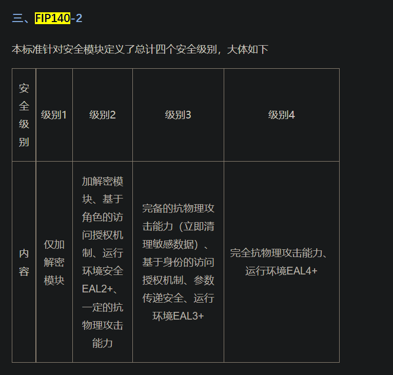
HSM 最重要的作用是安全边界, 和trustzone的机制类似, 提供安全的物理隔离能力, 安全rom和安全ram 无法被外部cpu 访问, 即使外部cpu 环境被破解, 也能保证hsm 运行的内容无法被探知. 当前的hsm产品中大多是过了FIPS 140-2 level3 标准的.

密钥存储/派生/权限管控/交换机制处于hsm内部(授信环境), 密钥存于安全rom或安全ram中, 无法被外部拿到.

与 只有硬件安全ip 加 otp 方案的对比

  1. 该方案密钥即使可以通过otp 管控密钥无法被外界拿到, 但也存在无法灵活配置, 很难做到密钥派生/密钥交换类似的需求, 在main域或其他域上的密钥更换是非常频繁的, 频繁的更换密钥能够保证前向安全(即如果密钥被泄露, 那hack 监听到的以往的数据都会变得不再安全)和重放攻击等. 比如https中使用的ssl/tls 加密机制, 每次建立连接后都是使用的新的密钥
  2. 芯片的安全ip采用的算法往往是对外公开的, 没有秘密可言. 相当于说是这种方案其实只有硬解加速的作用, 一旦密钥被探知, 那整个安全链路系统是非常脆弱的.
  3. hsm上执行的程序, 中间过程会锁在安全rom 安全ram内, 这种hsm 上跑的软件上层的机制其实也是安全的. 而只有安全ip的方案, 无论是做驱动还是什么都可以被探知破解.

HSM在智能汽车中应用的场景

阅读全文 »

stm32WB55

规格

STM32WB无线微控制器基于运行于64 MHz的Arm® Cortex®‐M4核心(应用处理器)和运行于32 MHz的Arm Cortex‐M0+核心(网络处理器)

时钟树 195

  1. HSE 时钟
    高速外部时钟信号(HSE)有2个时钟源 196
  • HSE 外部晶振
  • HSE 用户外部时钟
  1. 外部晶振(HSE晶振) [001](外部晶振(HSE 晶振))
    32 MHz 外部振荡器的优点是主时钟精度非常高

  2. 外部源(HSE旁路) 196
    由于生产工艺和所使用的晶振不同,不同芯片的HSE振荡器频率也不同。用户可以通过写入RCC时钟HSE寄存器(RCC_HSECR)中的HSETUNE位来调整应用中的HSE频率。 197

  3. HSI16时钟 197
    HSI16 时钟信号是从 16 MHz 内部振荡器生成的。
    HSI16 振荡器的优点是成本较低(无需使用外部元件)。此外,其启动速度也要比 HSE 晶振快,但即使校准后,其精度也不及外部晶振或陶瓷谐振器。

HSI16时钟还可作为备份时钟源(辅助时钟)使用,以防HSE晶振发生故障 197

  1. MSI时钟 197
阅读全文 »